Magnum MS2012 Inverter Troubleshooting: 8 Essential Methods for Quick Solution
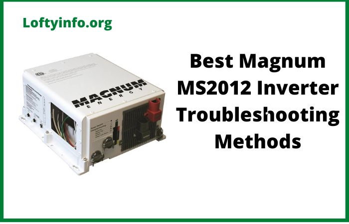
The Magnum Energy MS2012 pure sine wave inverter is a reliable power solution for RVs, boats and off-grid applications.
Like any electronic device, it can experience issues that require systematic troubleshooting.
This comprehensive guide covers proven methods to diagnose and resolve common MS2012 inverter problems, helping you restore power quickly and efficiently.
Understanding Your Magnum MS2012 Inverter
Before diving into troubleshooting methods, it’s essential to understand that the MS2012 is a 2000 watt pure sine wave inverter that converts 12V DC battery power to 120V AC household power.
Its sophisticated design includes built-in protection circuits, LED status indicators and multiple safety features that can sometimes trigger shutdowns to protect your equipment.
Best Magnum MS2012 Inverter Troubleshooting Methods
Method 1: LED Status Indicator Analysis
The first and most crucial troubleshooting step involves interpreting the LED status indicators on your MS2012 inverter.
These lights provide immediate diagnostic information about your inverter’s condition.
Green LED (Normal Operation): A solid green light indicates the inverter is functioning correctly and supplying clean AC power.
If this light is on, your inverter is operating within normal parameters.
Red LED Patterns: Different red LED patterns indicate specific problems:
- Solid Red: Indicates an overload condition where the connected load exceeds the inverter’s 2000-watt capacity
- Flashing Red (Fast): Signals low battery voltage, typically below 10.5V DC
- Flashing Red (Slow): Indicates high battery voltage, usually above 15.5V DC
- Alternating Red/Green: Shows the inverter is in search mode, looking for AC loads
Troubleshooting Steps:
- Document the exact LED pattern you’re observing
- Refer to your MS2012 manual for specific LED interpretations
- Address the underlying cause based on the LED indication
- Monitor the LEDs after making corrections to ensure proper operation
Understanding these indicators helps you quickly identify whether the problem is related to power overload, battery issues or internal inverter faults.
Method 2: Battery Voltage and Connection Inspection
Battery-related issues account for approximately 70% of inverter problems.
The MS2012 requires a stable 12V DC input to function correctly, making battery system inspection critical.
Voltage Testing Procedure: Use a digital multimeter to measure battery voltage at multiple points.
Start by checking voltage directly at the battery terminals, which should read between 12.6V (rested) and 14.4V (charging) for healthy batteries.
Magnum RV Inverter Troubleshooting
Next, measure voltage at the inverter’s DC input terminals.
A significant voltage drop between these two points indicates connection problems.
Connection Analysis: Inspect all DC connections for corrosion, looseness, or damage.
The MS2012 draws substantial current (up to 200 amps at full load), making secure connections essential. Look for:
- White or green corrosion on battery terminals
- Loose or oxidized cable connections
- Undersized cables that may cause voltage drop
- Damaged or frayed wiring
Battery Load Testing: Perform a load test by operating the inverter under moderate load while monitoring battery voltage.
Healthy batteries should maintain voltage above 12.0V under load.
If voltage drops rapidly below 11.5V, battery replacement may be necessary.
Corrective Actions: Clean all connections with a wire brush and apply dielectric grease to prevent future corrosion.
Tighten all connections to manufacturer specifications, typically 25-30 ft-lbs for battery terminals.
Replace any damaged cables with properly sized conductors (minimum 4/0 AWG for the MS2012).
Method 3: Load Assessment and Management
Overloading is a common cause of MS2012 shutdowns and can damage both the inverter and connected equipment if not properly addressed.
Load Calculation Process: Create a comprehensive inventory of all devices connected to your inverter.
List each device’s wattage rating which is usually found on a label or in the owner’s manual.
Pay special attention to devices with motors, compressors or heating elements as these often have startup surges significantly higher than their running wattage.
Understanding Surge vs. Continuous Loads: The MS2012 can handle 2000 watts continuously but provides surge capacity up to 4000 watts for brief periods.
This surge capability is limited to a few seconds.
Devices like refrigerators, air conditioners and power tools often require 2-5 times their running wattage during startup.
Load Management Strategies: Implement a systematic approach to load management:
- Prioritize essential loads during low battery conditions
- Stagger startup of high-surge devices to prevent simultaneous power draws
- Use energy-efficient appliances when possible
- Consider installing a load management system for automatic load shedding
Monitoring Tools: Install a battery monitor or inverter remote control panel to track real-time power consumption.
This helps you understand your usage patterns and identify power-hungry devices that may be causing problems.
Method 4: Temperature and Ventilation Optimization
The MS2012 inverter generates significant heat during operation and relies on proper ventilation for reliable performance.
Overheating can cause shutdowns, reduced efficiency and premature component failure.
Temperature Monitoring: The MS2012 includes internal temperature sensors that trigger shutdowns when safe operating temperatures are exceeded.
Normal operating temperature ranges from 32°F to 104°F (0°C to 40°C).
Beyond this range, the inverter may reduce output or shut down entirely.
Ventilation Requirements: Ensure adequate airflow around the inverter by maintaining minimum clearances:
- 4 inches on all sides for air circulation
- 6 inches above and below for convection cooling
- Unobstructed airflow paths to prevent heat buildup
Installation Considerations: Avoid installing the inverter in confined spaces without ventilation, such as closed cabinets or compartments.
If cabinet installation is necessary, add ventilation fans to ensure adequate air circulation.
Consider the ambient temperature of the installation location, as hot engine rooms or sunny locations can significantly impact inverter performance.
Cooling Improvements: For installations in challenging thermal environments, consider:
- Adding auxiliary cooling fans to improve airflow
- Installing heat shields to protect from radiant heat sources
- Relocating the inverter to a cooler location if possible
- Using thermal compound on mounting surfaces to improve heat transfer
Regular cleaning of cooling fins and air passages helps maintain optimal thermal performance and extends inverter life.
Method 5: AC Output Testing and Verification
Systematic AC output testing helps identify whether problems originate in the inverter itself or in connected loads and wiring.
Voltage Testing Procedure: Using a true RMS digital multimeter, measure AC output voltage at the inverter terminals with no load connected.
The MS2012 should output 120V ±5% (114V-126V) with clean sine wave characteristics.
Test both hot-to-neutral and hot-to-ground voltages to ensure proper output.
Frequency Verification: Check output frequency, which should be stable at 60Hz ±0.1Hz.
Frequency instability can indicate internal inverter problems or issues with the DC input voltage regulation.
Load Testing Protocol: Perform systematic load testing by connecting known-good loads of increasing wattage:
- Start with a 100-watt incandescent bulb to verify basic operation
- Gradually increase load in 200-500 watt increments
- Monitor voltage stability and inverter temperature during each test
- Note any load level where problems begin to occur
Waveform Analysis: If available, use an oscilloscope to examine the AC output waveform.
The MS2012 produces a pure sine wave that should appear smooth and symmetrical.
Distorted waveforms can indicate internal component problems requiring professional service.
Ground Fault and Safety Testing: Verify proper grounding by measuring resistance between the inverter case and the DC negative terminal, which should be less than 1 ohm.
Test GFCI functionality if your installation includes ground fault protection.
Method 6: Remote Control and Communication Diagnostics
The MS2012 can be equipped with various remote controls and monitoring systems that may affect operation or provide diagnostic information.
Remote Control Functionality: If your system includes a remote control panel (such as the Magnum ME-RC50), verify proper communication between the remote and inverter.
Check for:
- Secure cable connections at both ends
- Proper cable routing away from high-current DC cables
- Correct cable pinout and wiring
- Firmware compatibility between devices
Communication Troubleshooting: Communication problems can cause erratic inverter behavior or prevent remote control operation.
Symptoms include:
- Intermittent or no remote control response
- Incorrect status displays
- Inability to change inverter settings
- Error messages on the remote display
Diagnostic Procedures: Test communication systems by:
- Disconnecting and reconnecting communication cables
- Checking cable continuity with a multimeter
- Verifying proper power supply to remote control units
- Updating firmware if applicable
Settings Verification: Review all programmed settings through the remote control or DIP switches on the inverter itself.
Incorrect settings for battery type, low voltage disconnect or search mode sensitivity can cause operational problems that mimic hardware failures.
Method 7: Systematic Component Isolation
When multiple components are interconnected, isolating individual elements helps pinpoint the source of problems.
Disconnection Strategy: Implement a systematic approach to component isolation:
- Disconnect all AC loads and test inverter with no load
- Remove battery charger connections if present
- Disconnect transfer switch or automatic switching equipment
- Isolate monitoring and control systems
Individual Component Testing: Test each component separately to identify the problematic element:
- Battery Testing: Test batteries independently of the inverter system
- Load Testing: Test questionable loads on utility power before connecting to inverter
- Cable Testing: Check DC and AC cables for proper continuity and insulation
Systematic Reconnection: After identifying and addressing problems, reconnect components one at a time while monitoring inverter operation.
This approach helps confirm that repairs were successful and prevents multiple problems from masking each other.
Documentation Process: Keep detailed records of your isolation testing, including:
- Which components were disconnected and in what order
- Test results at each stage
- Any changes in inverter behavior
- Final configuration that restored proper operation
Method 8: Professional Service and Warranty Considerations
Some MS2012 inverter problems require professional diagnosis and repair, particularly those involving internal component failures or complex system interactions.
When to Seek Professional Help: Consider professional service when:
- Internal component failure is suspected
- Warranty coverage applies to your situation
- Safety concerns exist with high-voltage or high-current systems
- Repeated problems occur despite following troubleshooting procedures
Preparing for Service: Before contacting Magnum Energy support or authorized service centers:
- Document all symptoms and LED patterns observed
- Record all troubleshooting steps attempted
- Note your inverter’s serial number and date of purchase
- Gather any error codes or diagnostic information from remote controls
Warranty Considerations: The MS2012 typically includes a limited warranty covering manufacturing defects.
However, warranty coverage may be voided by:
- Improper installation or operation
- Damage from overvoltage or overcurrent conditions
- Physical damage or modification of the unit
- Operation outside specified environmental conditions
Service Options: Magnum Energy offers several service options:
- Technical Support: Phone and email support for troubleshooting assistance
- Authorized Service Centers: Professional repair facilities with factory training
- Return-to-Factory Service: Comprehensive testing and repair at Magnum facilities
Cost-Benefit Analysis: Before proceeding with professional service, consider the repair cost versus replacement cost, especially for older units. Factor in:
- Age and remaining useful life of the inverter
- Cost of professional diagnosis and repair
- Availability of newer, more efficient models
- Warranty coverage on repairs versus new equipment
Preventive Maintenance for Long-Term Reliability
Implementing a regular maintenance schedule helps prevent many common MS2012 problems and extends inverter life.
Monthly Inspections:
- Check all DC and AC connections for tightness and corrosion
- Clean cooling air passages and check for obstructions
- Test battery voltage and specific gravity (for flooded batteries)
- Verify proper LED operation and status indications
Quarterly Maintenance:
- Perform load testing to verify full power output capability
- Check and clean all electrical connections
- Test ground fault and safety systems
- Update any connected monitoring system software
Annual Service:
- Professional inspection of internal components if accessible
- Calibration verification of voltage and frequency output
- Thermal imaging to identify hot spots or component stress
- Complete system documentation update
Conclusion
Successful MS2012 inverter troubleshooting requires a systematic approach that addresses the most common failure modes while building diagnostic skills for complex problems.
By following these detailed methods from basic LED analysis to professional service considerations you can quickly identify and resolve most inverter issues while minimizing downtime and preventing costly damage to your electrical system.
Remember that safety should always be your primary concern when working with high-current DC systems and AC electrical equipment.
When in doubt, consult with qualified professionals who have experience with Magnum Energy products and off-grid power systems.
Regular maintenance, proper installation and understanding your system’s limitations are the keys to long-term reliability and trouble-free operation of your MS2012 inverter.
By implementing these troubleshooting methods and preventive maintenance practices, you’ll maximize your investment and ensure reliable power when you need it most.
