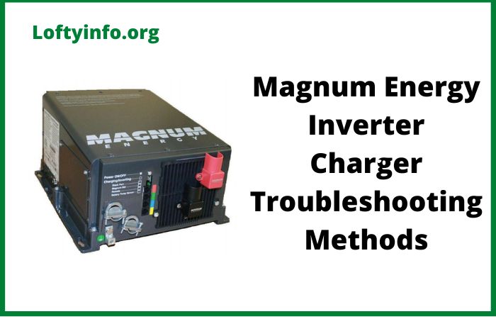
Magnum Energy Inverter Charger Troubleshooting: Best Methods to Fix Common Issues
When your Magnum Energy inverter charger stops working properly, it can disrupt your entire off-grid power system.
Whether you’re living in an RV, running a solar setup or managing backup power for your home, understanding how to troubleshoot these units is crucial for maintaining reliable electricity.
This comprehensive guide covers eight detailed troubleshooting methods that will help you diagnose and resolve the most common Magnum inverter charger problems.
Understanding Your Magnum Energy Inverter Charger Before Troubleshooting
Before diving into specific troubleshooting methods, it’s important to understand what your Magnum Energy inverter charger does.
These units serve dual purposes: they convert 12V, 24V or 48V DC power from your batteries into 120V AC power for your appliances (inverter function) and they also charge your batteries when connected to shore power or a generator (charger function).
Common models include the MS Series, MSH Series and MMS Series, each with specific features and troubleshooting considerations.
Magnum Energy Inverter Charger Troubleshooting Best Methods
Method 1: Check Power Connections and Battery Voltage
The Problem: Poor connections are the leading cause of inverter charger failures. Loose, corroded or improperly sized wiring can cause voltage drops, overheating and complete system failures.
Step-by-Step Solution:
Start by turning off all power sources and ensuring safety.
Use a digital multimeter to measure the voltage at your battery bank.
For a 12V system, you should see between 12.6V and 13.2V when the batteries are at rest.
For 24V systems, look for 25.2V to 26.4V and for 48V systems, expect 50.4V to 52.8V.
Next, inspect all DC connections between the batteries and inverter.
Look for green or white corrosion around terminals, which indicates oxidation that increases resistance.
Remove the cables and clean both the cable ends and terminals with a wire brush or sandpaper until you see bright metal.
Apply a thin layer of dielectric grease to prevent future corrosion.
Check that all connections are tight using the proper torque specifications found in your manual.
Loose connections create resistance, which generates heat and reduces power transfer efficiency.
Verify that your DC wiring is appropriately sized for the amperage your inverter draws.
Undersized wiring causes voltage drops that can trigger low-voltage shutdowns.
Why This Works: Clean, tight connections ensure maximum power transfer and prevent the voltage drops that cause most inverter protection circuits to activate.
Method 2: Verify and Reset Protection Settings
The Problem: Magnum inverters have multiple protection circuits that shut down the unit when parameters exceed safe limits.
These include over-voltage, under-voltage, over-temperature and overload protections.
Step-by-Step Solution:
Access your inverter’s control panel or remote display to check for error codes.
Common codes include “01” for low battery voltage, “02” for high battery voltage, “03” for over-temperature and “04” for overload conditions.
Each code points to a specific issue that needs addressing.
For low voltage shutdowns (typically occurring around 10.5V for 12V systems), first verify your battery voltage with a multimeter.
If batteries are actually low, charge them before attempting to restart the inverter.
If battery voltage is adequate but the inverter still shows low voltage, check for voltage drops in your DC wiring.
For over-voltage protection (usually triggered above 15.5V for 12V systems), this often indicates a charging system malfunction.
Check your solar charge controller, alternator or other charging sources for proper voltage regulation.
Temperature-related shutdowns require checking the inverter’s ventilation.
Ensure cooling fans are working and air vents aren’t blocked.
Clean accumulated dust from heat sinks and internal components using compressed air.
To reset protection circuits, follow the shutdown procedure in your manual, wait for the unit to cool down, then restart following the proper sequence.
Why This Works: Understanding and properly resetting protection circuits prevents unnecessary worry while ensuring your system operates safely within designed parameters.
Method 3: Test and Calibrate Battery Bank Performance
The Problem: Degraded or mismatched batteries can cause inverter chargers to malfunction, especially during high-current draws or charging cycles.
Step-by-Step Solution:
Begin by performing a comprehensive battery test.
Disconnect the battery bank from all loads and charging sources, then let it rest for at least four hours to get accurate voltage readings.
Use a digital multimeter to measure the voltage of each battery individually.
In a series configuration, batteries should be within 0.1V of each other.
Perform a load test using either a dedicated battery load tester or by connecting a known load and monitoring voltage drop.
A healthy 12V battery should maintain above 10.5V when loaded to 50% of its amp-hour capacity for 30 seconds.
Check battery specific gravity if you have flooded lead-acid batteries.
Use a hydrometer to test each cell, looking for readings between 1.265 and 1.300 for a fully charged battery.
Significant variations between cells (more than 0.030) indicate a failing battery.
For battery banks with multiple batteries, ensure all batteries are the same age, type and capacity.
Mixed battery types or ages create imbalances that stress both the batteries and the inverter charger.
If you find weak batteries, replace them with identical units.
When replacing batteries in a bank, it’s often best to replace all batteries simultaneously to maintain balance.
Why This Works: A healthy, balanced battery bank provides stable voltage and current, preventing the fluctuations that trigger inverter protection circuits.
Method 4: Examine AC Output Quality and Waveform
The Problem: Poor AC output quality can cause connected appliances to malfunction or refuse to operate, even when the inverter appears to be working.
Step-by-Step Solution:
Use a digital multimeter set to AC voltage to measure the output at the inverter’s AC terminals.
You should see 120V ± 5% (114V to 126V) for North American models.
Significant deviations indicate internal problems with the inverter’s transformer or control circuits.
Check the AC frequency using a frequency meter or oscilloscope.
Standard frequency should be 60Hz ± 0.1Hz. Frequency instability can cause motors to run hot and electronic devices to malfunction.
If possible, use an oscilloscope to examine the AC waveform.
Magnum pure sine wave inverters should produce a smooth sinusoidal wave.
Modified sine wave models produce a stepped approximation.
Look for excessive distortion, flat-topping or irregular patterns that indicate internal component failures.
Test the AC output under various load conditions.
Start with no load, then progressively add resistive loads (like incandescent lights), inductive loads (motors) and electronic loads (computers).
Monitor both voltage stability and waveform quality as loads change.
Check for proper grounding of the AC output.
The neutral and ground should be bonded at the inverter (unless using a separate bonding point) and properly grounded to your electrical system’s earth ground.
Why This Works: Quality AC output ensures your appliances receive clean, stable power while identifying internal inverter problems that might not be obvious from DC measurements alone.
Method 5: Diagnose Charging System Malfunctions
The Problem: The charger portion of your inverter charger may fail to properly charge batteries, leading to shortened battery life and eventual system failure.
Step-by-Step Solution:
Connect your inverter charger to AC input power (shore power or generator) and monitor the charging process.
Use a DC ammeter to measure charging current flowing to your batteries.
Initially, you should see high current (up to the charger’s rated output) that gradually decreases as batteries reach full charge.
Verify charging voltages at different stages. During bulk charging, expect to see 14.4V to 14.8V for 12V systems (double for 24V, quadruple for 48V).
During absorption phase, voltage should hold steady while current decreases.
Float voltage should settle around 13.2V to 13.6V for 12V systems.
Check that charging profiles match your battery type.
AGM, gel and flooded batteries require different charging voltages and algorithms.
Consult your inverter manual to verify proper settings for your battery chemistry.
Monitor charging temperature compensation.
Many Magnum units include temperature sensors that adjust charging voltage based on battery temperature.
Verify the sensor is properly connected and positioned near the batteries.
Test the AC input circuit by measuring voltage and frequency at the inverter’s AC input terminals.
Poor incoming power quality can disrupt charging operations.
If charging appears weak or non-existent, check internal fuses or circuit breakers dedicated to the charging circuit.
These may fail independently of the inverter circuits.
Why This Works: Proper charging is essential for battery longevity and system reliability.
Identifying charging problems early prevents costly battery replacement and system downtime.
Method 6: Resolve Inverter Shutdown and Restart Issues
The Problem: Inverters that shut down unexpectedly or fail to restart properly often have underlying issues with control circuits, thermal management or power supply problems.
Step-by-Step Solution:
Document the circumstances surrounding shutdowns.
Note the loads connected, ambient temperature, battery voltage and any error codes displayed.
This information helps identify patterns and root causes.
Check internal cooling systems.
Remove the inverter cover (with power disconnected) and inspect cooling fans for proper operation.
Fans should spin freely without excessive noise or wobbling.
Replace any failed fans immediately, as overheating is a primary cause of shutdowns.
Examine internal connections and components for signs of overheating, such as discolored components, melted insulation or burnt odors.
Pay particular attention to high-current connections and power semiconductors.
Test the inverter’s internal power supply circuits.
Many inverters have small internal power supplies that operate control circuits.
Use a multimeter to verify these provide stable voltages (often 12V or 15V) to control boards.
Perform a systematic restart procedure.
Turn off all AC loads, disconnect AC input power, wait for all capacitors to discharge (at least 5 minutes), then restart following the proper sequence outlined in your manual.
Check for software or firmware issues.
Some Magnum units allow firmware updates that can resolve operational problems.
Consult with Magnum technical support to determine if updates are available for your model.
Why This Works: Systematic diagnosis of shutdown issues identifies whether problems are electrical, thermal or control-related, allowing for targeted repairs rather than component replacement guesswork.
Method 7: Address Ground Fault and Electrical Safety Issues
The Problem: Ground faults and electrical safety issues can cause inverters to shut down, create safety hazards or damage connected equipment.
Step-by-Step Solution:
Test all grounding connections using a low-resistance ohmmeter.
The resistance between the inverter chassis, AC equipment grounding conductor and system earth ground should be less than 0.1 ohms.
High resistance indicates poor connections that need cleaning and retightening.
Use a GFCI tester on any GFCI-protected outlets connected to your inverter.
Ground fault protection may be built into the inverter or provided by downstream devices.
Verify proper operation by pressing test and reset buttons.
Check for ground loops by temporarily disconnecting non-essential ground connections and observing system behavior.
Multiple ground paths can create circulating currents that trigger protection devices.
Verify proper neutral-to-ground bonding.
In most installations, neutral and ground are bonded at the inverter but this varies by installation type and local codes.
Incorrect bonding can cause nuisance tripping and safety issues.
Use an insulation tester (megohmmeter) to check insulation resistance between conductors and ground.
Readings should exceed 1 megohm for most installations.
Low readings indicate insulation breakdown that requires immediate attention.
Inspect all wiring for damage, particularly looking for nicks in insulation, pinched wires or areas where wires might contact sharp edges.
Even small insulation defects can cause ground faults.
Why This Works: Proper grounding and electrical safety practices prevent dangerous conditions while ensuring reliable inverter operation and compliance with electrical codes.
Method 8: Perform Advanced Diagnostic Testing and Component Analysis
The Problem: Some inverter problems require deeper analysis of internal components and circuits that basic troubleshooting cannot identify.
Step-by-Step Solution:
Begin with a comprehensive visual inspection of internal components.
Look for swollen or leaking capacitors, which appear bulged at the top or have visible electrolyte leakage.
Failed capacitors are common in aging inverters and affect both power quality and reliability.
Test key semiconductors using appropriate test equipment.
Power MOSFETs and IGBTs can fail partially, causing reduced performance rather than complete failure.
Use a semiconductor tester or oscilloscope to verify proper switching operation.
Measure transformer winding resistance and insulation.
Use a low-resistance ohmmeter to compare primary and secondary winding resistances against manufacturer specifications.
Insulation between windings and from windings to core should exceed 10 megohms.
Check control board operations by monitoring control signals with an oscilloscope.
Look for proper PWM (pulse-width modulation) signals, gate drive voltages and feedback signals. Irregular control signals indicate board-level failures.
Test internal current sensors and voltage feedback circuits.
These components provide information to the control circuits about system operation.
Failed sensors can cause improper regulation or protection circuit malfunctions.
Perform thermal imaging of internal components under load conditions (using appropriate safety precautions).
Hot spots indicate failing components, poor connections or inadequate cooling.
Consider professional repair for component-level failures unless you have appropriate skills and test equipment.
Many internal components require specialized handling and calibration.
Why This Works: Advanced diagnostics identify specific failed components rather than guessing, leading to more effective repairs and preventing collateral damage from continued operation with failing parts.
When to Seek Professional Help
While these troubleshooting methods can resolve many common issues, some problems require professional service.
Contact a qualified technician or Magnum Energy support when:
- You find evidence of internal component failure
- Troubleshooting reveals multiple simultaneous problems
- Safety concerns arise during inspection
- Warranty coverage might be affected by DIY repairs
- You lack the proper test equipment for advanced diagnostics
Preventive Maintenance for Long-Term Reliability
Regular maintenance prevents many of the problems covered in this troubleshooting guide:
- Clean air filters and vents monthly
- Check and tighten all connections quarterly
- Monitor battery condition and charging performance regularly
- Keep firmware updated when updates are available
- Maintain detailed logs of system performance and any issues
Conclusion
Troubleshooting Magnum Energy inverter chargers requires a systematic approach that progresses from basic checks to advanced diagnostics.
By following these eight detailed methods, you can identify and resolve most common problems while avoiding unnecessary repairs or replacements.
Remember that prevention through regular maintenance is always preferable to emergency troubleshooting and don’t hesitate to seek professional help when safety or complex component failures are involved.
Understanding your system’s normal operation makes abnormal conditions easier to spot and diagnose.
Keep this guide handy as a reference and consider creating a maintenance log to track your system’s performance over time.
With proper care and systematic troubleshooting, your Magnum Energy inverter charger can provide years of reliable service for your power needs.