High Frequency Inverter Technical Specifications Explained
When it comes to inverter technology, high frequency is the new normal.
These are light weight inverters that use smaller transformers as compared to low frequency inverters that use larger size transformers.
High frequency inverters are also more energy efficient as compared to low frequency inverters.
In this guide, we will look at the technical specification of high frequency inverters.
High Frequency Inverter Technical Specifications
In explaining the technical specification of high frequency inverters, we will categorize the specifications into 3 groups.
They are;
inverter capacity specification, inverter input specification and inverter output specification.
A) Inverter Capacity Specifications
1) Rated Power
Rated power represents the continuous power output that an inverter can deliver under normal operating conditions without overheating or damage.
This specification is typically expressed in watts (W) or kilowatts (kW) and indicates the maximum load the inverter can sustain indefinitely.
For example, a 3000W rated inverter can continuously power devices totaling up to 3000 watts.
This rating assumes optimal operating conditions including proper ventilation, appropriate ambient temperature and correct DC input voltage.
Understanding rated power is crucial for system sizing, as it determines what appliances and loads can be operated simultaneously.
2) Surge Power
Surge power also known as peak power defines the maximum power an inverter can deliver for short durations, typically lasting from a few seconds to several minutes.
This specification addresses the high initial power draw of inductive loads such as motors, compressors and transformers during startup.
These devices often require 2-7 times their running power during the first few seconds of operation.
A quality inverter might have a surge power rating of 150% to 200% of its rated power allowing it to handle these temporary power spikes without shutting down or triggering protective circuits.
3) DC Input Type
The DC input voltage specification determines the battery bank configuration required for the inverter.
Common voltage levels include 12V, 24V and 48V systems.
Lower voltage systems (12V) are typically used in smaller applications like RVs and boats, while higher voltage systems (48V) are preferred for larger residential and commercial installations.
Higher voltage systems offer several advantages including reduced current flow, smaller wire requirements, lower losses and improved efficiency.
The choice of DC input voltage affects the entire system design, including battery configuration, wiring requirements and safety considerations.
4) Efficiency
Efficiency measures how effectively an inverter converts DC power to AC power expressed as a percentage.
Modern high frequency inverters typically achieve efficiencies between 90% to 96%.
This specification is crucial because it determines how much battery power is lost as heat during the conversion process.
Higher efficiency means longer battery runtime, reduced cooling requirements and lower operating costs.
Efficiency can vary with load conditions typically peaking at 40-80% of rated load and decreasing at very light or very heavy loads.
Understanding efficiency curves helps optimize system performance and battery life.
5) Inverter Technology – High Frequency
High frequency inverter technology utilizes switching frequencies typically ranging from 20kHz to 100kHz significantly higher than traditional low frequency inverters that operate around 50Hz to 60Hz.
This technology offers several advantages including smaller transformer size, reduced weight, lower manufacturing costs and faster response times.
High frequency inverters use pulse width modulation (PWM) or similar techniques to create clean sine wave outputs.
They may be more sensitive to certain loads and require more sophisticated control circuits compared to their low frequency counterparts.
6) Number of MPPTs
MPPT count indicates how many independent solar array inputs the inverter can handle.
Each MPPT circuit can optimize power extraction from a separate solar panel string or array section.
Multiple MPPTs provide flexibility in system design allowing panels with different orientations, tilt angles or shading conditions to operate independently.
For instance, an inverter with two MPPTs can handle east and west-facing panel arrays separately optimizing power generation from each orientation throughout the day.
More MPPTs generally mean better system performance but also increased complexity and cost.
B) Inverter Input Specifications
1) DC Input Voltage
This specification defines the acceptable range of DC voltage that the inverter can operate within.
It typically includes minimum startup voltage, nominal operating voltage and maximum allowable voltage.
For a 48V system, the DC input range might be 40V to 60V DC, accommodating battery voltage variations during charging and discharging cycles.
The inverter must operate efficiently across this entire range while providing protection against under voltage and over voltage conditions.
This range directly correlates with battery chemistry and configuration choices.
2) Maximum DC Input Current
Maximum DC input current represents the highest current the inverter can safely draw from the DC source, typically the battery bank.
This specification is crucial for proper fusing, wiring and battery bank sizing.
It’s calculated based on the inverter’s maximum power output divided by the minimum DC input voltage.
For example, a 5000W inverter operating at 48V minimum might draw up to 105A DC current (5000W ÷ 48V).
Understanding this specification ensures proper electrical protection and prevents damage to the inverter’s input circuits.
3) AC Input Range
The AC input range specifies the acceptable voltage and frequency limits for grid connection when the inverter includes battery charging capabilities.
This range typically accommodates normal grid voltage variations and minor frequency deviations.
For example, a North American unit might accept 108V to 132V AC at 60Hz ±3%.
This specification ensures the inverter can maintain proper operation during normal grid voltage fluctuations while disconnecting safely during abnormal conditions.
It also determines the inverter’s ability to function in different geographical regions with varying grid standards.
4) PV Input Voltage Range
Another important high frequency inverter technical specifications is PV input voltage range.
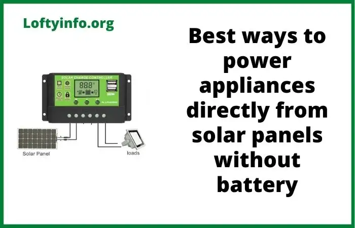
This is what determines if your high frequency inverter can easily power appliances directly from power from the solar panels or not.
When the input voltage from the solar panel is high, the inverter will easily power appliances from the solar panel energy.
But if the voltage input range is low, it will not be able to easily power appliances directly from the solar panels without the help of the battery.
The PV input voltage range defines the solar panel voltage window within which the MPPT controllers can effectively track maximum power points.
This range typically spans from a minimum voltage required for MPPT operation to a maximum safe voltage limit.
For instance, an MPPT might operate from 60V to 150V DC allowing flexibility in solar panel series connections.
Operating within this range ensures optimal power extraction from solar panels under varying temperature and irradiance conditions.
Voltages outside this range may result in reduced efficiency or protective shutdown.
5) Maximum PV Input Current
This specification indicates the highest current that each PV input can safely handle from connected solar panels.
It determines the maximum number of parallel panel strings that can be connected to each MPPT input.
Exceeding this current rating can damage the inverter’s PV input circuits or trigger protective shutdowns.
For example, if an MPPT input is rated for 25A maximum and each panel string produces 10A, then two parallel strings would be the safe limit.
This specification is critical for proper solar array design and electrical protection.
6) Maximum PV Array Power
Maximum PV array power defines the total solar panel wattage that can be connected to each MPPT input or the entire inverter.
This limitation ensures the MPPT circuits and internal components are not overloaded by excessive solar power generation.
It’s important to note that this rating considers standard test conditions (STC) and actual field conditions may allow for higher panel ratings due to real-world derating factors.
Understanding this specification helps optimize solar array sizing while maintaining safe operating conditions.
C) Inverter Output Specifications
1) DC Battery Charging Amps
This specification indicates the maximum current the inverter can deliver to charge connected batteries when AC power is available.
The charging current is typically adjustable and determines how quickly batteries can be recharged from grid power or generator input.
Higher charging currents reduce charging time but may require more robust battery systems capable of accepting high charge rates.
This specification must be matched to battery manufacturer recommendations to ensure safe charging and optimal battery life.
2) AC Output Voltage
AC output voltage specifies the nominal voltage delivered by the inverter to connected loads.
Common specifications include 120V, 240V or 120/240V split-phase for North American applications or 230V for European systems.
This voltage must remain stable across varying load conditions and DC input voltages.
The inverter’s voltage regulation circuits maintain output voltage within acceptable limits regardless of input voltage variations or load changes.
Proper voltage output ensures connected equipment operates safely and efficiently.
3) Output Voltage Range
Output voltage range measures how well the inverter maintains stable output voltage under varying load and input conditions.
Typically expressed as a percentage.
This specification indicates the maximum voltage deviation from nominal under normal operating conditions.
Better regulation (smaller percentage) means more stable power for sensitive electronics.
For example, ±2% regulation on 120V output means voltage stays between 117.6V and 122.4V.
Superior voltage regulation protects connected equipment and ensures optimal performance of sensitive loads.
4) Output Frequency
Output frequency specification defines the AC frequency produced by the inverter typically 50Hz or 60Hz depending on regional standards.
Modern inverters include frequency regulation specifications usually within ±0.1Hz of nominal frequency.
Stable frequency is crucial for timing-sensitive equipment, motors and appliances.
Some inverters offer frequency adjustment capabilities for specific applications.
The inverter must maintain frequency stability across varying load conditions and during transitions between different operating modes.
5) Waveform
Waveform specification describes the shape and quality of the AC output signal.
High-quality inverters produce pure sine wave output that closely matches utility grid power.
This specification often includes total harmonic distortion (THD) ratings typically less than 3% for premium units.
Pure sine wave output ensures compatibility with all types of loads including sensitive electronics, motors and audio equipment.
Poor waveform quality can cause equipment malfunction, increased power consumption, audible noise and reduced equipment lifespan.
6) Maximum Solar Charging Current
Maximum solar charging current specifies the highest current the inverter can deliver to batteries from connected solar panels.
This rating determines how quickly batteries can be charged directly from solar power and affects system autonomy and battery cycling.
The charging current is typically adjustable to match battery specifications and optimize charging profiles.
Higher solar charging currents enable faster battery recharging and better system performance during periods of high solar irradiance.
This specification must be coordinated with battery charge acceptance rates and thermal management capabilities.
Knowing these high frequency inverter technical specifications will help in design and optimal sizing of the inverter system.