Common Growatt SP2000 Problems and Solutions
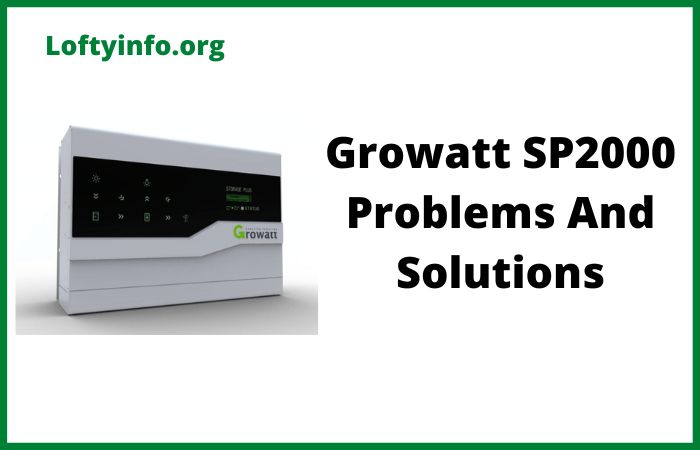
The Growatt SP2000 is a popular energy storage system designed to work between solar panels and inverters in residential photovoltaic installations.
This DC battery controller enables homeowners to store excess solar energy for later use during nighttime or periods of low generation.
While the SP2000 offers significant benefits for energy independence, users frequently encounter several technical issues that can disrupt system performance.
Understanding these problems alongside their causes and solutions helps owners maintain optimal operation of their solar battery storage systems.
Common Growatt SP2000 Problems
1) BMS Communication Fault (Error 500/116)
The battery management system communication error represents one of the most frequently reported issues with the SP2000 unit.
This problem manifests when the controller cannot establish or maintain proper communication with the connected battery pack.
The display typically shows messages indicating BMS COM Fault or Error 116, signaling a breakdown in data exchange between components.
The primary cause involves faulty or improperly connected ethernet cables between the SP2000 and the battery.
Physical damage to RJ45 connectors, loose connections, or using incorrect cable types can prevent proper signal transmission. Additionally, incompatible third-party batteries that don’t use Growatt’s communication protocol can trigger this error even when physical connections appear correct. Firmware mismatches between the controller and battery firmware versions also contribute to communication failures.
To resolve this issue, first power down the entire system by switching off the circuit breaker followed by the Socomec switches.
Inspect the ethernet cable connecting the SP2000 to the battery for any visible damage, bends, or loose connections.
Replace the cable if necessary, ensuring you use a standard ethernet cable rather than a crossover type.
Verify that both ends of the cable are firmly seated in their respective ports.
For systems using lithium batteries, confirm the battery type setting in the SP2000 matches the actual battery installed.
Check that the cable connects to the correct RS485 port on the battery (typically the first RJ45 port in the RS485 section).
After securing all connections, power up the system by first connecting the battery, then the SP2000, followed by the AC supply.
Allow several minutes for the system to establish communication.
If the error persists, access the SP2000 settings through ShineLink software to verify firmware compatibility between controller and battery.
In cases where non-Growatt batteries are installed, consider switching the SP2000 to lead-acid mode as this may allow operation without BMS communication, though with reduced functionality.
2) Temperature-Related Errors
Temperature problems frequently affect SP2000 performance, particularly in installations located in poorly ventilated spaces like attics or lofts.
The system displays errors such as Bat T Outrange when battery temperatures fall outside acceptable operating parameters.
Both excessively high and low temperatures can trigger protective shutdowns that prevent charging or discharging operations.
The SP2000 relies on natural cooling through radiator vents since it lacks internal fans.
When installed in enclosed spaces with poor air circulation, heat accumulates around the unit during operation.
Summer temperatures combined with inadequate ventilation can push internal temperatures beyond safe limits.
During cold weather, condensation can form on electronic components when temperature drops significantly.
Extreme cold also affects battery chemistry, particularly in lead-acid batteries where low temperatures reduce capacity and increase internal resistance.
Missing or faulty NTC temperature sensors in lead-acid battery configurations prevent the system from accurately monitoring battery temperature, leading to false temperature readings or error codes.
For overheating issues, ensure the installation location provides adequate ventilation with unrestricted airflow around all sides of the unit.
The radiator must have clear space above it for hot air to escape naturally.
Consider relocating the SP2000 if the current position lacks proper ventilation, particularly if it sits in direct sunlight or near heat sources.
Install additional ventilation in the installation room or use passive cooling methods like ventilation grilles.
Regularly clean dust and debris from radiator fins and air passages to maintain optimal cooling efficiency.
For cold weather problems, verify that the installation environment maintains temperatures within the specified range of 0 to 40 degrees celsius.
When condensation becomes an issue, improve room insulation and consider using a dehumidifier to reduce moisture levels.
Never operate the system when visible water or moisture appears on components or connections.
For lead-acid battery systems, check that the NTC temperature sensor properly adheres to the battery cabinet top surface.
The sensor must make good contact for accurate readings.
If the sensor is missing or damaged, replace it with a 10k ohm NTC thermistor connected to pins 2 and 6 of the temperature sensor port.
In lithium battery systems, ensure the battery’s internal temperature management system functions correctly as it communicates temperature data to the SP2000 via the ethernet connection.
3) AC Connection and Voltage Range Errors (Error 300/302/304)
Users frequently encounter errors related to AC mains connection and voltage parameters.
These faults appear as No AC Connection (Error 302) or AC V Outrange/AC F Outrange (Error 300/304), indicating the SP2000 cannot detect proper grid connection or the mains voltage/frequency exceeds configured safety thresholds.
The SP2000 requires a continuous AC power supply to operate even though it functions as a DC battery controller.
Without AC connection, the unit cannot initiate its control systems or monitor grid conditions.
Loose or disconnected AC power cables create intermittent or complete loss of mains connection.
Incorrect wiring between the AC supply and the SP2000 also prevents proper operation.
Voltage and frequency errors occur when grid conditions fluctuate outside the safety parameters configured for your region.
The SP2000 sets these parameters based on local electrical safety standards and when measured values exceed upper or lower limits, the system triggers protective shutdown.
Power grid instability, particularly in areas with unreliable electricity supply, can cause frequent triggering of these protection mechanisms.
Incorrect country or region settings in the SP2000 configuration may apply inappropriate voltage and frequency ranges that don’t match your actual grid parameters.
Begin troubleshooting by verifying the AC power lead is securely plugged into both the SP2000 and a working electrical outlet.
Test the outlet with another device to confirm it provides power. Inspect the AC cable for any damage, cuts, or exposed wires that might indicate connection problems.
Ensure the cable gauge meets the recommended specification of at least 3 x 0.75mm² conductor size. C
heck that circuit breakers and isolation switches feeding the SP2000 remain in the on position.
For voltage range errors, use a multimeter to measure the actual grid voltage at the installation point.
Compare this reading to the configured voltage range in the SP2000 settings.
If grid voltage consistently falls outside normal parameters, contact your electricity supplier as this indicates a broader grid quality issue.
Access the SP2000 configuration through the ShineLink software to verify the country/region setting matches your actual location.
Incorrect regional settings may apply voltage ranges unsuitable for your grid.
During installation or after any electrical work, confirm all wiring follows proper polarity with phase, neutral, and ground connections made correctly.
Loose neutral connections particularly can cause voltage irregularities. If voltage range errors occur intermittently during peak usage times, this suggests grid voltage fluctuations beyond system tolerance.
Consider installing a voltage stabilizer or working with your electricity provider to improve supply quality. Reset the system after correcting any wiring issues by powering down completely for at least five minutes before restart.
4) PV Short Circuit and IGBT Failure
Hardware component failures occasionally affect SP2000 units, with PV short circuit faults and blown IGBT transistors representing serious internal problems.
These failures prevent the unit from processing solar panel input and require component-level repair rather than simple troubleshooting.
IGBT (Insulated Gate Bipolar Transistor) components on the SP2000 main circuit board handle power conversion between the PV input and battery/inverter output.
These semiconductors operate under high voltage and current conditions, making them susceptible to failure from electrical surges, overvoltage conditions or manufacturing defects.
When one IGBT fails, it often creates a short circuit condition that can damage adjacent components.
Lightning strikes or severe voltage spikes from the solar array can instantly destroy multiple IGBTs simultaneously.
Inadequate heat dissipation due to failed thermal pads or improper mounting can cause thermal stress leading to transistor failure over time.
Once IGBTs fail, the unit displays PV short circuit errors and ceases normal operation.
This problem requires technical expertise and component-level repair skills.
Before attempting any internal work, follow the official shutdown procedure and completely disconnect all power sources including PV panels, inverter connections, AC mains, and battery.
The unit must have no electrical connections whatsoever before opening the case.
Discharge any residual capacitance by waiting at least 30 minutes after disconnection. Remove the unit’s cover using appropriate screwdrivers (Phillips and Torx T15 required).
Locate the main circuit board and visually inspect IGBTs for obvious damage like burn marks, cracks, or discoloration.
The SP2000 typically uses two types of transistors: IRFP4110PBF MOSFETs on top positions and IGBT modules on bottom positions.
Use a multimeter to test each transistor’s junctions following proper IGBT testing procedures.
Healthy IGBTs show specific resistance values between gate, collector, and emitter terminals.
Any transistor showing short circuit or open circuit conditions requires replacement.
When replacing failed components, best practice dictates replacing all transistors in the same row even if only one shows failure, as the electrical stress that destroyed one component likely weakened others.
Remove failed transistors using a desoldering tool or desoldering braid, taking care not to damage circuit board traces. Clean the mounting pads thoroughly before installing new components.
Apply new thermal interface pads between transistors and heat sinks to ensure proper heat transfer. Solder replacement transistors ensuring good solder joints without cold joints or bridges between pins.
Reassemble the unit carefully, ensuring all screws and connections return to their original positions. Before reconnecting to the system, perform continuity tests to verify no short circuits exist between power rails.
This repair requires soldering skills and electronic component knowledge; users uncomfortable with these procedures should seek professional repair services rather than risk further damage.
5) MPPT Configuration Problems with Dual Tracker Inverters
Installation configuration errors frequently cause problems when the SP2000 connects to inverters with dual MPPT tracking capability.
Users often misunderstand the SP2000’s single MPPT limitation and attempt configurations that create power flow conflicts.
The SP2000 contains only one MPPT tracker despite having multiple input and output terminals.
This design works perfectly with single MPPT inverters or when connecting to just one tracker of a dual MPPT inverter. However, problems arise when installers try to utilize both MPPT inputs of a dual-tracker inverter through the SP2000.
Many users assume the SP2000’s two output terminals represent separate MPPT channels, but internally they connect to the same power rail.
When both outputs feed separate MPPT inputs on an inverter, the two MPPTs compete for power, each trying to control voltage and current independently.
This creates oscillating power conditions where output swings between the two channels as each MPPT fights for control.
The result is unstable operation, reduced efficiency, and potential shutdown conditions.
Connecting PV arrays with significantly different characteristics (different orientations like east/west, different shading patterns or unequal panel numbers) to the single SP2000 MPPT input creates suboptimal power harvesting.
The single tracker must find a compromise operating point that doesn’t maximize output from either array.
For systems with dual MPPT inverters, select the configuration that best suits your installation needs.
Option one involves connecting only one PV array through the SP2000 to one inverter MPPT input, leaving the second array connected directly to the second inverter MPPT input.
This configuration allows both MPPT trackers to operate independently but means only the array passing through the SP2000 can charge the battery.
The second array’s generation goes directly to the grid or loads without storage capability.
Choose to route the larger or better-performing array through the SP2000 to maximize battery charging potential.
Option two uses both arrays through the SP2000 to a single inverter MPPT input, but only works well when both arrays have very similar characteristics.
Arrays must have matching orientations, minimal shading differences, and similar voltage ratings. Even slight mismatches can cause the single MPPT to operate below optimal point for one or both arrays.
Never connect the SP2000’s two output terminals to two different MPPT inputs on the same inverter as this creates the fighting MPPT condition described earlier.
For split-roof installations with panels facing different directions (east/west configurations), strongly consider option one where different array orientations connect to separate MPPT trackers.
This allows each tracker to independently optimize its assigned array’s output throughout the day as sun angles change.
For installations requiring maximum battery charging from multiple arrays, installing two complete SP2000 systems (one for each MPPT channel) provides optimal performance but at significantly higher cost.
During installation planning, carefully evaluate your PV array configuration, roof orientations, and shading patterns against the SP2000’s single MPPT limitation. In some cases, accepting that only one array charges the battery while maintaining optimal harvesting from all arrays represents the best practical compromise.
Update system documentation to clearly note which arrays connect through battery storage versus direct grid connection to avoid future confusion during maintenance or system modifications.
Conclusion
The Growatt SP2000 energy storage system delivers valuable battery storage capabilities for residential solar installations when properly configured and maintained.
Most common problems stem from communication issues, environmental factors, incorrect configuration or component failures.
Regular system monitoring through the Growatt online portal helps identify developing issues before they cause complete system failure.
Maintaining proper environmental conditions with adequate ventilation and temperature control prevents many temperature-related problems.
Ensuring all connections remain secure and using appropriate cables eliminates communication faults. Understanding the system’s single MPPT limitation during initial installation prevents configuration errors that reduce performance.
For complex problems involving internal component failures, seeking assistance from qualified solar technicians or Growatt certified installers ensures proper diagnosis and repair. Preventive maintenance including periodic visual inspections, connection checks and firmware updates extends system lifespan and maintains reliable operation.
By understanding these common problems and their solutions, SP2000 owners can maximize their investment in solar energy storage while minimizing downtime and frustration.
Why is my Livguard inverter battery not charging
Bluetti ac200p problems and solutions explained
