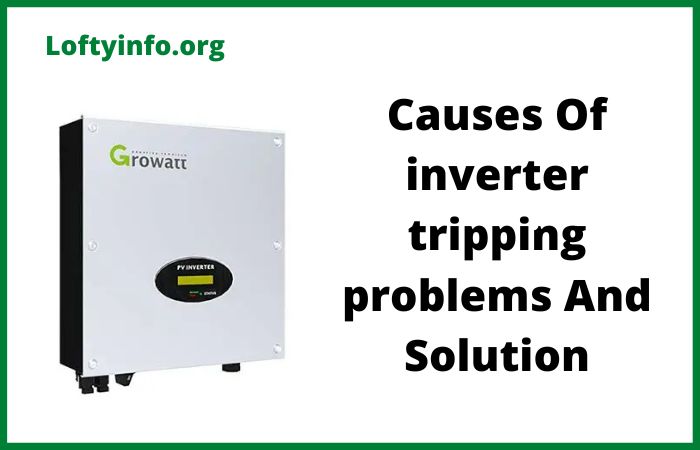
Common Growatt SPF 5000 ES Problems and Solutions
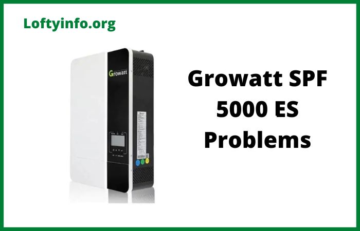
The Growatt SPF 5000 ES is a popular off-grid solar inverter that combines solar charging capabilities with battery storage and grid backup functionality.
This 5000 watt hybrid inverter has gained widespread adoption among homeowners and businesses seeking reliable solar power solutions.
While the unit offers impressive features including MPPT charge control and compatibility with various battery types, users frequently encounter specific operational challenges that can impact system performance.
Understanding these common problems and their solutions is essential for maintaining optimal inverter performance.
This guide explores the most frequently reported issues affecting the Growatt SPF 5000 ES along with detailed troubleshooting steps.
Growatt SPF 5000 ES Problems
1) Solar Power Not Generating Despite Adequate Voltage
Many users report situations where the inverter displays proper voltage from solar panels but shows zero current flow.
The LCD screen may show voltage readings between 290V and 350V yet current remains at 0 amperes.
This problem typically occurs after the system has been operating normally for several weeks or months.
The root cause often relates to exceeding the maximum input current specification.
The SPF 5000 ES has an 18 amp maximum PV input current limit and configurations that exceed this threshold will experience power cutoffs.
Parallel panel strings commonly push beyond this limit particularly when using high-current panels.
Another frequent cause involves incorrect panel polarity where reversed connections trigger the MPPT controller’s protective mode.
Less commonly, panel configuration creates voltage drops below the 150VDC startup threshold.
To resolve this issue, first verify your total panel current does not exceed 18 amperes at maximum output.
Calculate the short circuit current of one string and multiply by the number of parallel strings.
If you exceed the limit, reconfigure panels into series strings rather than parallel connections.
A series configuration typically produces more usable power while respecting current limitations.
Check panel polarity at both the combiner box and inverter terminals using a multimeter.
If polarity is reversed, disconnect all power sources before correcting the wiring.
Measure your panel voltage during problem periods. If voltage drops below 150VDC, add panels in series to maintain adequate startup voltage.
2) Error Code 02 Overheating and Cooling System Failures
Error code 02 appears when the inverter’s internal temperature exceeds safe operating limits.
This fault causes automatic shutdown and displays warning indicators on the LCD screen.
Users often encounter this problem during hot weather or after several months of continuous operation.
Overheating problems stem from several causes.
Inadequate ventilation around the installation location prevents proper heat dissipation.
Fan malfunctions including locked fans significantly reduce cooling capacity.
Dust and debris accumulation on cooling fins and internal components acts as insulation that traps heat. High ambient temperatures in equipment rooms push the inverter beyond its thermal design limits.
Begin troubleshooting by powering down the inverter and allowing it to cool for at least 30 minutes. Inspect cooling fans for physical obstructions or debris.
Clean all visible dust from exterior cooling fins using compressed air.
Ensure the installation location provides adequate clearance with at least 12 inches of space above and below the unit.
Check that ambient temperature stays within 0 to 50 degrees Celsius.
If the fan motor fails to spin when power is applied, fan replacement is necessary.
3) Battery Drainage Problems and Incorrect Bypass Behavior
A critical problem involves unexpected battery drainage when the system should switch to grid bypass mode.
The inverter fails to properly transfer to utility power when the battery state of charge reaches the programmed cutoff threshold.
Batteries continue discharging well below safe levels sometimes reaching 1% capacity despite settings that should trigger bypass at 20% or higher.
The inverter’s power consumption including fans and control circuitry draws power from the battery system even during bypass mode.
This parasitic draw depletes batteries when solar power is inadequate.
Bypass switching mechanisms also suffer from firmware bugs that prevent proper grid connection.
Settings interactions between program 01, program 12 and program 21 can create conditions where the inverter fails to execute proper switching.
Set the AC input current to 2 amperes or higher to cover the inverter’s idle power consumption.
Verify program 21 is set to at least 20% rather than very low values.
Update the inverter firmware to the latest version as several releases specifically address bypass switching problems.
In parallel installations, disconnect and reconnect battery connections and current sharing cables to reset control logic.
If bypass failures continue, manually cycling the grid breaker forces the inverter to re-evaluate its operating mode.
4) Inconsistent or Incomplete Battery Charging
Owners experience batteries that fail to charge to full capacity or that charge inconsistently despite adequate solar power.
The system may show charging activity but stops unexpectedly before batteries reach 100%.
Charging current fluctuates wildly or drops to minimal levels when robust charging should occur.
Incorrect voltage settings in programs 19 and 20 represent the most common cause.
When bulk and float charging voltages are set too low for specific battery chemistry, the BMS prevents full charging.
Lack of proper BMS communication means the inverter cannot receive accurate battery status information. Firmware issues in some units cause inconsistent charging patterns.
For lithium iron phosphate batteries, set program 19 to 55.6V and program 20 to 54.4V as baseline values then adjust based on manufacturer recommendations.
Establish proper BMS communication by connecting the battery’s CAN or RS485 cable to the inverter’s BMS port.
For proper connection, ensure the communication cable uses correct pin mapping with pins 7 and 8 on the battery side connecting to pins 4 and 5 on the inverter side.
If using user-defined battery settings without BMS communication, carefully verify all voltage parameters match your battery specifications.
Check absorption time and charging current settings to ensure adequate charging duration.
A firmware update often resolves charging inconsistencies particularly for older units.
5) Unexpected Switching to Grid Bypass
Users report the inverter switching to grid bypass mode when battery state of charge remains well above the configured threshold.
The system may operate on utility power when batteries show 30% to 50% charge despite settings that should prioritize battery usage.
When the inverter operates in bypass mode due to insufficient PV power, fans running off the battery create a charge discharge cycle that can trigger premature bypass switching.
Program settings interactions create complex switching logic that produces unexpected results.
Voltage measurement discrepancies between the inverter’s readings and actual battery voltage cause incorrect switching decisions.
Optimize program 01 based on your usage pattern.
The SBU mode typically provides best results for systems with adequate solar and battery capacity.
Adjust program 12 to trigger bypass at a lower battery percentage if you want to maximize battery utilization.
Set program 21 higher than program 12 to create proper hysteresis that prevents rapid switching between modes.
Set utility charging current in program 11 to 1 ampere to prevent the inverter’s power consumption from depleting batteries during bypass mode.
Perform a firmware update to address timing and logic bugs.
After reconfiguring settings, monitor behavior across several charge cycles to verify proper switching occurs.
Conclusion
The Growatt SPF 5000 ES provides capable off-grid power when properly configured and maintained but requires attention to several common problem areas.
Most issues stem from incorrect settings, inadequate system sizing or firmware limitations rather than fundamental design flaws.
Success depends on careful attention to specifications particularly the 18-amp PV input current limit and proper battery voltage configuration.
Regular maintenance including cooling system cleaning and connection tightness checks prevents many problems before they cause failures.
Establishing proper BMS communication with lithium batteries improves charging reliability and battery longevity.
Firmware updates address numerous operational bugs and should be applied when available from Growatt support.
common solaredge inverter problems
Growatt inverter troubleshooting
Common growatt sp2000 problems and solutions
Causes of growatt pv isolation low fault
Why common growatt inverter problems occur
How to choose solar system type wisely and avoid funds wastage
Factors to consider when choosing battery for your solar setup
Luminous zelio 1100 inverter problems
Luminous inverter battery charging problem
Complete 146 john deere loader specs
Common 1586 international problems
