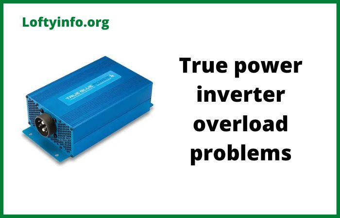
True Power Inverter Overload Problems: Causes and Solutions
Power inverters have become essential devices in modern homes and businesses, converting DC power from batteries into usable AC power for household appliances and electronic equipment.
While these devices offer tremendous convenience, they are not immune to operational challenges.
Among the most common issues users face are overload problems that can compromise inverter performance and potentially damage connected equipment.
Understanding true power inverter overload problems is crucial for anyone relying on these devices for backup power or off-grid applications.
An overload occurs when the total power demand from connected devices exceeds the inverter’s rated capacity, triggering protective mechanisms that shut down the system.
These problems can manifest in various ways, from sudden shutdowns during operation to complete system failures that require technical intervention.
This comprehensive guide explores the most prevalent overload issues affecting true power inverters, examining their underlying causes and providing practical solutions.
Whether you experience frequent tripping, voltage fluctuations or unexplained shutdowns, understanding these problems will help you maintain optimal inverter performance and extend the lifespan of your power backup system.
True Power Inverter Overload Problems
1) Sudden System Shutdown During Normal Operation
One of the most frustrating overload problems involves the inverter shutting down unexpectedly while powering devices well within its supposed capacity.
Users often report that their inverter turns off without warning even when the connected load appears to be significantly below the rated output.
The primary cause of this issue stems from inrush current demands that occur when certain appliances start up.
Motors in refrigerators, air conditioners and power tools can draw three to seven times their normal operating current during the first few seconds of operation.
This surge momentarily exceeds the inverter’s capacity, triggering the overload protection circuit. Additionally, the inverter’s continuous power rating may be lower than its peak rating, and many users mistakenly calculate their load based on peak specifications rather than continuous output capacity.
Another contributing factor involves aging battery banks that cannot deliver sufficient current to meet sudden power demands.
When batteries deteriorate, their internal resistance increases, limiting the amount of current they can supply to the inverter.
This creates a bottleneck that appears as an overload condition even though the inverter itself is capable of handling the load.
To resolve sudden shutdown issues, start by calculating the actual continuous power rating of your inverter and ensure your total load remains at least twenty percent below this threshold to account for efficiency losses.
Identify appliances with high inrush currents and avoid starting multiple high-draw devices simultaneously. Consider installing a soft-start device on motors and compressors to reduce startup current spikes.
Test your battery bank under load to verify it can deliver adequate current, and replace aging batteries that show signs of degradation such as reduced capacity or excessive voltage drop under load.
Installing a battery monitor system helps track real-time current draw and identify problematic usage patterns.
2) Voltage Fluctuation and Output Instability
Inverters experiencing overload conditions often exhibit unstable output voltage that fluctuates between acceptable and unacceptable levels.
Connected devices may flicker, reset unexpectedly or display error messages indicating power problems. This instability can damage sensitive electronics and reduce the lifespan of connected equipment.
Voltage fluctuations during overload typically result from the inverter operating at the edge of its capacity where the internal voltage regulation system struggles to maintain stable output.
When power demand approaches or exceeds the rated capacity, the inverter’s components heat up and efficiency drops, causing output voltage to sag.
Poor connections between the inverter and battery bank also contribute to voltage instability.
Loose terminals or corroded connections create resistance that causes voltage drops under load, making the inverter appear overloaded even when it is not.
Undersized wiring between batteries and inverter represents another common cause.
If the cables cannot handle the required current flow, voltage drops occur along the cable length, reducing the effective voltage available to the inverter.
This forces the inverter to draw even more current to compensate, creating a cascading effect that leads to unstable output and potential shutdown.
Address voltage fluctuation problems by first inspecting all electrical connections between the batteries and inverter.
Clean any corroded terminals using a wire brush and baking soda solution, then apply dielectric grease to prevent future corrosion.
Tighten all connections to manufacturer specifications using a torque wrench.
Verify that cable sizes meet the inverter manufacturer’s recommendations based on the maximum current draw and cable length.
Upgrade to larger gauge cables if necessary, keeping in mind that cable size requirements increase with both current and distance.
Install the inverter as close to the battery bank as practical to minimize cable length. Monitor the voltage at both the battery terminals and inverter input under load using a digital multimeter.
If significant voltage drop occurs between these points, the wiring infrastructure needs upgrading.
Consider adding a voltage stabilizer on the output side for particularly sensitive equipment.
3) Thermal Overload and Inadequate Cooling
Power inverters generate substantial heat during operation, and this heat production increases dramatically as the load approaches maximum capacity.
Thermal overload occurs when the inverter’s internal temperature exceeds safe operating limits, triggering thermal protection circuits that shut down the system to prevent component damage.
The root causes of thermal overload often relate to inadequate ventilation around the inverter installation.
Many users install inverters in enclosed spaces without sufficient airflow, causing heat to accumulate around the device.
Dust accumulation on cooling fans and heat sinks further reduces cooling efficiency. The inverter’s ambient operating environment also plays a critical role.
Operating an inverter in high-temperature locations such as unventilated storage rooms or direct sunlight significantly reduces its effective capacity because the device starts from a higher baseline temperature.
Extended operation near maximum capacity generates more heat than the cooling system can dissipate, even with adequate ventilation.
Inverters typically include derating curves that show how capacity decreases with temperature, but users rarely consult these specifications.
A 3000-watt inverter rated for 25 degrees celsius might only safely deliver 2400 watts at 40 degrees celsius without triggering thermal shutdown.
Resolve thermal overload issues by relocating the inverter to a well-ventilated area away from direct heat sources and sunlight.
Ensure minimum clearance specifications are maintained on all sides of the unit as specified in the installation manual. Install additional cooling fans to improve air circulation around the inverter if natural ventilation proves insufficient.
Clean the inverter’s cooling fans and heat sinks regularly using compressed air to remove accumulated dust and debris.
Consider the ambient temperature in your capacity calculations and reduce the connected load accordingly in hot weather.
Some installations benefit from air conditioning in the inverter room, particularly in tropical climates or during summer months.
Monitor the inverter’s internal temperature using built-in temperature sensors or external thermal monitoring equipment.
If the inverter consistently runs hot even with improved ventilation, the connected load may be too high for sustained operation and should be reduced.
4) Harmonic Distortion and Waveform Quality Issues
Less obvious but equally problematic are overload conditions caused by harmonic distortion in the inverter’s output waveform.
While the total power draw may appear within acceptable limits, certain types of loads create harmonic feedback that the inverter interprets as an overload condition, leading to shutdown or reduced output.
This problem primarily affects modified sine wave inverters when powering inductive loads such as motors, transformers and certain battery chargers.
These devices draw current in non-linear patterns that create harmonic distortions on the power line.
The inverter must supply additional current to compensate for these harmonics, effectively increasing the real load beyond what a simple wattage calculation would suggest.
Switch-mode power supplies in modern electronics also generate harmonics that add to the burden on the inverter.
When multiple harmonic-generating devices operate simultaneously, their combined effect can push the inverter into overload even though the cumulative rated wattage remains below capacity.
The inverter’s internal filters and regulation circuits must work harder to maintain output quality, increasing component stress and heat generation.
This situation becomes particularly problematic with lower-quality inverters that have limited filtering capabilities.
Address harmonic-related overload problems by upgrading to a pure sine wave inverter if currently using a modified sine wave unit.
Pure sine wave inverters produce cleaner output that reduces harmonic generation and improves compatibility with sensitive loads.
Calculate the actual power factor and harmonic content of your loads rather than relying solely on rated wattage.
Power factor correction equipment can help improve efficiency and reduce the apparent load on the inverter.
Separate harmonic-generating loads onto different circuits when possible to prevent cumulative effects. Install line filters on particularly problematic devices to reduce harmonic feedback into the inverter.
Consider using a power quality analyzer to measure actual current harmonics and identify specific devices causing problems.
Some advanced inverters include adjustable sensitivity settings for overload detection that can be calibrated to accommodate moderate harmonic content without nuisance tripping.
5) Battery Bank Capacity Mismatch and Runtime Limitations
A frequently overlooked overload scenario involves mismatched battery capacity that cannot sustain the inverter’s rated output for meaningful durations.
While the inverter may technically be capable of producing the rated power, the battery bank cannot supply sufficient energy to maintain that output level, resulting in rapid voltage collapse and system shutdown.
This problem occurs when users select inverter capacity based solely on peak power requirements without considering the battery amp-hour capacity needed to support that load.
A 5000-watt inverter drawing from a small battery bank might operate for only minutes before the batteries deplete to the low-voltage cutoff point, triggering what appears to be an overload shutdown.
The actual issue involves energy storage capacity rather than power delivery capability.
Battery age and condition significantly impact this scenario.
As batteries age, their effective capacity diminishes while their internal resistance increases.
A battery bank that originally provided adequate runtime gradually becomes insufficient, leading to increasingly frequent shutdowns under load.
Temperature effects also reduce battery capacity, with cold conditions particularly detrimental to performance. A battery bank that performs adequately in summer may prove inadequate during winter months.
Resolve battery capacity mismatch issues by calculating the actual amp-hour requirements for your desired runtime at the intended load.
A basic formula involves dividing the total watt-hours needed by the battery bank voltage and then multiplying by 1.2 to account for inefficiency.
For a 3000-watt load running for 2 hours on a 48-volt system, you need approximately 150 amp-hours of usable capacity.
Add sufficient battery capacity to meet these requirements, remembering that deep-cycle batteries should typically not be discharged below 50 percent capacity for longevity.
Test your battery bank regularly using a capacity tester to identify degraded cells before they impact system performance.
Replace the entire battery bank rather than mixing old and new batteries, as mismatched batteries create imbalances that reduce overall performance.
Implement a battery temperature compensation system for the charging circuit to ensure batteries remain properly charged across varying temperature conditions.
Consider upgrading to lithium batteries if using lead-acid technology, as lithium batteries maintain voltage better under load and offer deeper discharge capability without damage.
Monitor individual battery voltages during discharge to identify weak batteries causing premature voltage collapse.
Understanding and addressing these true power inverter overload problems ensures reliable operation and extends the service life of both the inverter and connected equipment.
Regular maintenance, proper sizing and careful load management prevent most overload situations before they become critical failures.
magnum RV inverter troubleshooting
Luminous Inverter Not Working After Power Cut Problem Causes And Solutions
Exide inverter overload trip problems
Microtek inverter overload problems
Understanding how inverter overload affects performance
Understanding amaron inverter overload problems
Solutions to Luminous inverter high voltage problems
Luminous inverter 650 overload problems with solutions
Growatt inverter troubleshooting
What growatt pv isolation low fault is
Common growatt inverter problems
Common victron inverter problem causes and solutions
Inverter transformer heating problems
