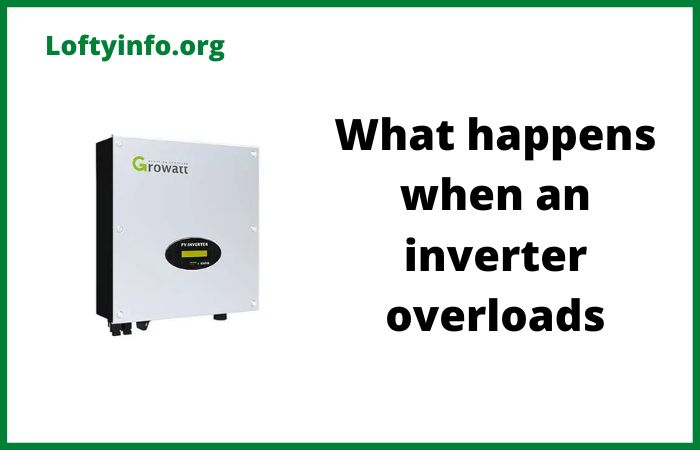
What Happens When an Inverter Overloads
Inverters are essential devices that convert direct current electricity into alternating current for powering household appliances and electronic equipment.
These units are rated for specific power capacities measured in watts or kilowatts and exceeding this capacity creates an overload condition.
Understanding what happens during inverter overload helps you prevent damage to your equipment and maintain reliable power supply for your home or business.
What Happens When an Inverter Overloads
1) Automatic Shutdown and Protection Mode Activation
The most immediate response to inverter overload is automatic shutdown as built-in protection circuits detect excessive power draw and cut off output to prevent damage.
Modern inverters incorporate sophisticated monitoring systems that continuously measure output current voltage and internal temperature.
When connected load exceeds the inverter’s rated capacity these sensors trigger within milliseconds to protect internal components from destructive stress.
The shutdown process follows a specific sequence designed to safely interrupt power flow. First the inverter’s microcontroller detects that output current has exceeded preset thresholds for a sustained period.
Most quality inverters allow brief surge currents to accommodate motor starting loads but continuous overcurrent triggers protection.
The control circuit then sends signals to power switching transistors or MOSFETs commanding them to stop conducting.
Output voltage drops to zero within a few milliseconds and connected appliances lose power immediately.
An alarm sounds on many models and indicator lights change from green to red or amber signaling the fault condition.
This protective shutdown prevents several catastrophic failure modes.
Excessive current through power transistors generates heat that can quickly exceed safe junction temperatures causing permanent semiconductor damage.
Transformer windings carrying overcurrent develop dangerous temperatures that degrade insulation and can lead to short circuits.
Circuit board traces may overheat and lift from the board or even vaporize under extreme overload.
Capacitors subjected to excessive ripple current can fail explosively.
The automatic shutdown mechanism essentially sacrifices your temporary power availability to preserve the inverter’s long-term functionality and prevent fire hazards.
After shutdown most inverters require manual intervention to restart.
You must disconnect some appliances to reduce total load below the rated capacity then press the reset button or power cycle the unit.
Some advanced models attempt automatic restart after a cooling period but will shutdown again if the overload persists.
This design forces users to address the root cause rather than repeatedly damaging the inverter through sustained overload operation.
2) Voltage Drop and Power Quality Degradation
Before reaching the shutdown threshold an overloaded inverter experiences significant voltage drop at its output terminals.
This voltage sag affects all connected equipment and creates various operational problems.
Standard inverters maintain output voltage within 5 percent of nominal under rated load but overload conditions can drop voltage by 10 to 20 percent or more depending on severity.
The voltage drop occurs because of fundamental electrical principles and inverter design limitations.
Power transistors have finite on-resistance that causes voltage loss proportional to current flow.
As load current increases this resistive drop becomes more pronounced. Transformers exhibit leakage inductance and winding resistance that similarly reduce output voltage under heavy load.
The inverter’s control loop attempts to compensate by increasing duty cycle or boost voltage but has limited correction range before reaching hardware limits.
Connected appliances respond poorly to reduced voltage. Electric motors draw higher current trying to maintain rated power output which paradoxically worsens the overload condition.
Motor windings overheat from excessive current flow potentially causing thermal failure. Compressors in refrigerators and air conditioners may fail to start or run inefficiently. Induction cooktops and electric heaters produce less heat than expected.
Electronic equipment with linear power supplies may malfunction or shut down as internal voltage rails drop below minimum specifications.
LED and CFL lighting dims noticeably and may flicker.
Voltage drop also degrades power quality in ways that stress electrical components. The inverter’s output waveform distorts from the ideal sinusoid as power circuits struggle to regulate under overload.
Total harmonic distortion increases substantially introducing higher frequency components into the output.
These harmonics create additional heating in transformer cores and motor windings.
Electronic equipment power supplies must work harder to filter distorted input waveforms reducing their efficiency and reliability.
Sensitive electronics like computers and audio equipment may experience glitches or data corruption from poor power quality.
The combination of low voltage and high distortion creates a hostile electrical environment. Even if the inverter doesn’t immediately shut down, your connected equipment suffers accelerated wear and potential damage.
This degraded operation mode cannot be sustained long-term without consequences for both the inverter and the appliances it powers.
3) Excessive Heat Generation and Component Stress
Overload conditions force inverter components to dissipate far more heat than their design specifications allow.
Power semiconductors, transformers and other elements generate waste heat proportional to the square of current flow meaning a 50 percent overload produces 2.25 times normal heat generation.
This thermal stress accelerates component aging and can trigger destructive thermal runaway if protection systems fail.
Power transistors and MOSFETs are the primary heat generators in modern inverters.
These devices switch high currents on and off thousands of times per second to synthesize AC output from DC input.
Each switching cycle involves brief periods when the device carries current while partially conducting resulting in power dissipation.
Conduction losses occur when fully on due to finite on-resistance. Both loss mechanisms increase dramatically with overload current. Junction temperature rises rapidly and may exceed the 150 to 175 degree Celsius ratings of typical semiconductors within seconds of severe overload.
Heat spreads from the semiconductor junctions through thermal interface materials to heatsinks then dissipates to ambient air through convection and radiation.
This thermal path has finite capacity determined by heatsink size, surface area and airflow. Overload heat generation easily overwhelms cooling capacity causing temperature rise throughout the inverter chassis.
Other nearby components including capacitors, resistors and integrated circuits experience elevated temperatures even if not directly in the power path.
Elevated temperature accelerates multiple failure mechanisms. Electrolytic capacitors are particularly vulnerable as their lifespan halves for every 10 degrees Celsius increase in operating temperature above ratings.
The liquid electrolyte gradually evaporates through seals causing capacitance loss and increased equivalent series resistance.
Solder joints develop thermal fatigue from repeated expansion and contraction cycles eventually cracking and creating intermittent connections.
Semiconductor junctions develop increased leakage current at high temperature reducing efficiency and potentially causing thermal runaway where leakage current creates additional heat in a self-reinforcing cycle.
Insulation materials in transformers and inductors degrade from heat exposure becoming brittle and prone to breakdown.
Cooling fans run continuously at maximum speed during overload trying to remove excess heat.
The constant high-speed operation accelerates bearing wear and the fans may fail prematurely.
Some inverter designs lack active cooling and rely entirely on passive heatsinks making them even more vulnerable to thermal damage during sustained overload.
Even after overload ends elevated temperatures persist for minutes to hours depending on thermal mass and cooling effectiveness.
4) Battery Drain and Reduced Runtime
For inverters powered by batteries such as in off-grid solar systems or backup power applications overload dramatically reduces available runtime.
Batteries must supply higher current to meet excessive load demands and this increased discharge rate reduces total energy delivery according to Peukert’s law.
The combination of lower capacity and higher consumption results in surprisingly short operation duration.
Peukert’s law describes how battery capacity decreases as discharge current increases. Lead-acid batteries rated at 100 amp-hours at the 20-hour rate may deliver only 70 to 80 amp-hours when discharged at higher rates typical of inverter overload.
Lithium batteries exhibit less capacity reduction but still suffer performance loss at extreme discharge rates.
This means the available energy is substantially less than the battery’s nameplate rating suggests.
The inverter itself operates less efficiently under overload compounding the battery drain problem.
Efficiency drops from typical values of 90 to 95 percent down to 80 percent or lower as losses increase disproportionately. More battery energy converts to waste heat rather than useful output power.
The combination of reduced battery capacity and lower inverter efficiency creates a multiplicative effect on runtime reduction.
High discharge current also generates heat within battery cells from internal resistance. Battery temperature rises during sustained overload discharge reducing voltage and available capacity further.
Very high discharge rates can damage battery plates through warping or active material shedding particularly in lead-acid types.
Lithium batteries may trigger internal protection circuits that limit current or shut down completely to prevent damage or safety hazards.
The battery voltage drops more rapidly under overload current due to internal resistance. Inverters monitor input voltage and implement low-voltage disconnect to protect batteries from over-discharge damage.
The inverter shuts down when battery voltage falls below preset thresholds which occurs much sooner under overload than normal load.
Your effective runtime may be only 20 to 30 percent of expected duration for the battery capacity.
5) Premature Aging and Reduced Lifespan
Repeated or sustained overload operation significantly shortens inverter lifespan through accumulated stress and wear on critical components.
Each overload event pushes parts beyond their design limits creating microscopic damage that accumulates over time. The inverter may continue functioning after individual overload incidents but fails prematurely compared to units operated within ratings.
Electrolytic capacitors suffer the most pronounced aging acceleration from overload conditions.
These components are often the lifespan-limiting elements in power electronics. Overload current increases ripple current through capacitors and elevated temperature from overload heat accelerates electrolyte evaporation.
Capacitors that might last 10 to 15 years under rated conditions may fail in 3 to 5 years with regular overload exposure.
Failed capacitors cause various symptoms including poor voltage regulation, increased output ripple and complete inverter failure.
Power semiconductors develop gradual parametric degradation from thermal and electrical stress.
Gate oxide in MOSFETs accumulates damage from voltage stress reducing reliability. Wire bonds connecting semiconductor dies to lead frames experience thermal cycling fatigue and may eventually crack.
These changes increase on-resistance and switching losses further increasing heat generation in a deteriorating cycle.
The devices eventually fail short or open circuit requiring expensive repairs or unit replacement.
Transformer and inductor insulation degrades from repeated thermal cycling during overload events.
The insulation coating on magnet wire develops microcracks from expansion and contraction.
Moisture and contaminants gradually penetrate compromised insulation reducing dielectric strength.
The transformer may eventually develop turn-to-turn or layer-to-layer shorts that manifest as reduced efficiency humming noise or complete failure.
Solder joints throughout the circuit board accumulate fatigue damage from thermal cycling. Each heating and cooling cycle causes differential expansion between components and the board creating mechanical stress.
Solder develops grain boundary cracks that propagate slowly until the joint fails creating intermittent or permanent open circuits.
These failures can be difficult to diagnose as they may occur in locations far from the obvious power path.
The cumulative effect of these aging mechanisms means an inverter subjected to frequent overload may fail when you need it most.
The unit provides increasingly unreliable service with more frequent shutdowns, erratic behavior and eventual complete failure.
Replacement costs far exceed the minor inconvenience of operating within rated capacity or upgrading to a larger inverter better suited to your actual power requirements.
why roof top solar panels catch fire
3176 cat engine complete technical specs
Critical mistakes to avoid when connecting solar panels in parallel
